|
ezLCD+103 Driver
0.1
Driver code for the ezLCD+103
|
Macros | |
| #define | EZLCD_WHITE 0xFF, 0xFF, 0xFF |
| #define | EZLCD_BLACK 0x00, 0x00, 0x00 |
| #define | EZLCD_BLUE 0x00, 0x00, 0xFF |
| #define | EZLCD_RED 0xFF, 0x00, 0x00 |
| #define | EZLCD_GREEN 0x00, 0xFF, 0x00 |
| #define | EZLCD_YELLOW 0xFF, 0xFF, 0x00 |
| #define | EZLCD_ORANGE 0xFF, 0xA5, 0x00 |
| #define | EZLCD_DARK_BLUE 0x00, 0x00, 0x8B |
| #define | EZLCD_VIOLET 0xEE, 0x82, 0xEE |
Functions | |
| void | ezLCD_set_color_rgb (uint8_t red, uint8_t green, uint8_t blue) |
| void | ezLCD_set_alpha (uint8_t alpha) |
| void | ezLCD_set__tr_color_rgb (uint8_t red, uint8_t green, uint8_t blue) |
| void | ezLCD_tr_color_none (void) |
| void | ezLCD_set_background_color (uint8_t red, uint8_t green, uint8_t blue) |
| void | ezLCD_replace_color (uint8_t o_red, uint8_t o_green, uint8_t o_blue, uint8_t n_red, uint8_t n_green, uint8_t n_blue) |
This header file is used to manage various color settings used when drawing objects to the ezLCD+103.
A number of functions in this category request RGB (Red, Green, Blue) color values. In the RGB color model, the colors red, green, and blue are added together in different quantities to form a new color as shown in the image below
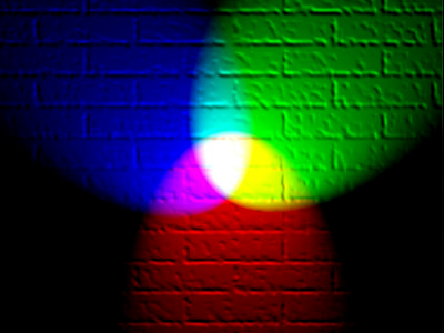
One can specify the quantity of each color with a one byte (8-bit) value for each of the red, green, and blue quantities. These values are added together to form a 24-bit number representing a new color. There are a total of 256^3 (or 2^24) possible colors in the RGB color model. This is a rather daunting number since there are quite a large number of colors to choose from. As a result, some macros have been provided in this header file which represent some common colors. They may be used in place of the three RGB parameters in any function in this file which requests them as in the shown code snippet below. The following two lines of code are equivalent.
These macros may also be used by the ezLCD_putchar_init() function, the ezLCD_fill_bound() function, or any function which requires all three RGB values (in that order).
If the user needs additional colors not defined in this file, there are a number of online resources, such as this one , which will help the user find the perfect color.
| #define EZLCD_BLACK 0x00, 0x00, 0x00 |
RGB values for the color black
| #define EZLCD_BLUE 0x00, 0x00, 0xFF |
RGB values for the color blue
| #define EZLCD_DARK_BLUE 0x00, 0x00, 0x8B |
RGB values for the color dark blue
| #define EZLCD_GREEN 0x00, 0xFF, 0x00 |
RGB values for the color green
| #define EZLCD_ORANGE 0xFF, 0xA5, 0x00 |
RGB values for the color orange
| #define EZLCD_RED 0xFF, 0x00, 0x00 |
RGB values for the color red
| #define EZLCD_VIOLET 0xEE, 0x82, 0xEE |
RGB values for the color violet
| #define EZLCD_WHITE 0xFF, 0xFF, 0xFF |
RGB values for the color white
| #define EZLCD_YELLOW 0xFF, 0xFF, 0x00 |
RGB values for the color yellow
| void ezLCD_replace_color | ( | uint8_t | o_red, |
| uint8_t | o_green, | ||
| uint8_t | o_blue, | ||
| uint8_t | n_red, | ||
| uint8_t | n_green, | ||
| uint8_t | n_blue | ||
| ) |
This function is used to replace a color within the rectangular region previously specified by the ezLCD_set_edit_rectangle() function
This function is used to set the transparent color of the display. Of course , the term transparent color is somewhat of an oxymoron. By color, we mean the color which is to be ignored during bitmap image drawing. Those students who have taken CSE 219 should be relatively familiar with this concept. Some bitmap image files, such as .jpg images, do not natively support transparency. However, in some situations, we would like to treat a portion of the image as transparent. In order to do this, we design the image with a "sacrificial" color which will not be painted to the screen when the image is drawn.
Suppose we have the image below:

Now suppose we choose our sacrificial color to be orange. When the image is drawn to the screen, the orange color will not be drawn; we will only see the red circle drawn to the screen as shown below.

| void ezLCD_set_alpha | ( | uint8_t | alpha | ) |
This function is used to set the transparency of the current color. It should be noted that any transparency other than 0 or 255 (fully transparent or fully opaque respectively) will result in objects being painted to the screen somewhat slower. Upon power-up, the default transparency is 255 (fully opaque).
This function is used to set the background color. By background color we do not mean the background of the entire display, but rather the "secondary color." This parameter is useful for some functions, such as ezLCD_putchar_bg(), which utilize a secondary color. The following code snippet will result in white text on a black background (for simplicity, assume that the ezLCD_init_putchar() function was already called):

This function is used to set the current color. This is used by a number of the display's drawing functions. Upon power-up the most recently used color prior to the last shutdown will be set as the current color. Bitmap images and fonts are NOT affected by this function.
| void ezLCD_tr_color_none | ( | void | ) |
This function is used to set the transparent color to "none". When called, every color in a bitmap image or font will be painted to the screen; no color will be ignored. For more information about transparent colors, see ezLCD_set__tr_color_rgb().
 1.8.5
1.8.5

