|
| void | ezLCD_draw_circle (uint16_t radius) |
| |
| void | ezLCD_draw_circle_fill (uint16_t radius) |
| |
| void | ezLCD_draw_arc (uint16_t radius, uint16_t start_angle, uint16_t end_angle) |
| |
| void | ezLCD_draw_pie (uint16_t radius, uint16_t start_angle, uint16_t end_angle) |
| |
| void | ezLCD_draw_ellipse (uint16_t semi_major_axis, uint16_t semi_minor_axis) |
| |
| void | ezLCD_draw_ellipse_fill (uint16_t semi_major_axis, uint16_t semi_minor_axis) |
| |
| void | ezLCD_draw_ellipse_arc (uint16_t semi_major_axis, uint16_t semi_minor_axis, uint16_t start_angle, uint16_t end_angle) |
| |
| void | ezLCD_draw_ellipse_pie (uint16_t semi_major_axis, uint16_t semi_minor_axis, uint16_t start_angle, uint16_t end_angle) |
| |
This header contains functions which aid in the drawing of curved objects such as circles, ellipses, arcs, and pies.
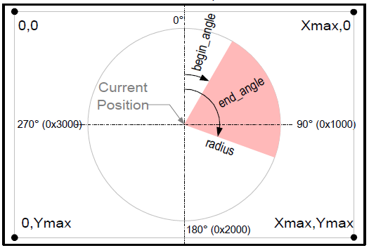
Like the EA DOGM128, angles are specified rather unconventionally. In this case, the unit circle is flipped along the line y=x, resulting in the following angle placements:
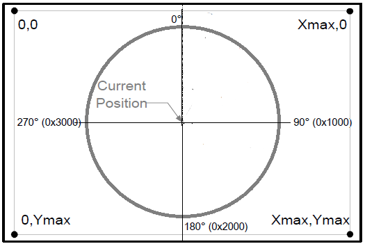
Angle placements on the ezLCD+103
Notice that 0 degrees is on the north pole of the Y-axis and 90 degrees is on the east end of the X-axis.
NOTE: The EZLCD+103 only understands positive angles from 0-360 degrees. It does not understand negative angles nor does it understand large angles such as 720 degrees. When supplying an angle to the ezLCD+103, it must be converted to a positive angle between 0 and 360 degrees. Supplying values outside of this range may result in unusual behavior and a sluggish display for some time while the display tries to interpret the angle. IT IS HIGHLY ENCOURAGED TO ONLY SUPPLY THE DISPLAY WITH ANGLES FROM 0-360 DEGREES!
Also similar to the EA DOGM128, angles are not specified in degrees and must be converted before being supplied to any functions in this file which may request angles. However, the ezLCD specifies angles with 16-bit precision rather than 8-bit precision. In order to convert from degrees to LCD angle units the user should use the following formula
LCD Angle Units = degrees * (2048)/45
So, for example:
- 360 degrees = 16384 LCD angle units = 0 LCD angle units = 0 degrees (due to 16-bit overflow).
- 90 degrees = 4096 LCD angle units
- 180 degrees = 8192 LCD angle units
- 270 degrees = 12288 LCD angle units
As was the case previously, fractional results from this equation should be rounded or truncated accordingly.
This function is used to draw an arc as shown below from the current position in the current color at the current pen width and current pen height .
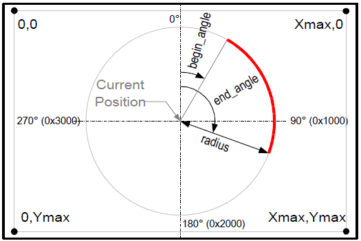
Arc
- Parameters
- radius = the radius of the arc in the set [0,65535].
- start_angle = the angle at which drawing will begin in the set [0,16384].
- end_angle = the angle at which drawing will end in the set [0,16384].
- Assumptions
- The user does not exceed the angle limits. The ezLCD+103 only understands positive angles from 0 to 360 degrees. Anything greater renders extremely slowly and is undefined.
- The user has set the current position ,the current color , the current pen width, and the current pen height
- The user has initialized the MCU's SPI interface with the EZLCD_INIT_SPI() macro.
- The user has set the MCU's SPI pins to inputs and outputs appropriately.
- SS_BAR = OUTPUT
- SCK = OUTPUT
- MOSI = OUTPUT
- MISO = INPUT
| void ezLCD_draw_circle |
( |
uint16_t |
radius | ) |
|
This function is used to draw an unfilled circle as shown below from the current position in the current color at the current pen width and current pen height .
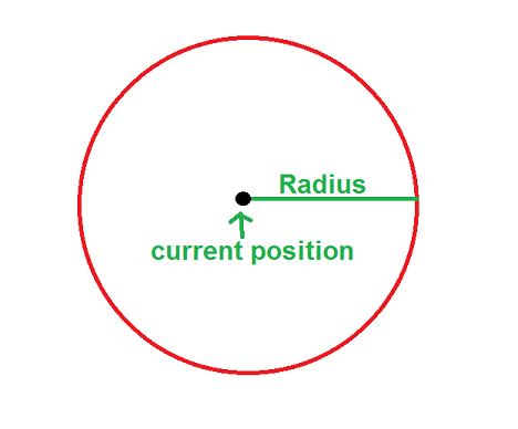
Unfilled Circle
- Parameters
- radius = the radius of the circle in the set [0,65535].
- Assumptions
- The user has set the current position ,the current color , the current pen width, and the current pen height
- The user has initialized the MCU's SPI interface with the EZLCD_INIT_SPI() macro.
- The user has set the MCU's SPI pins to inputs and outputs appropriately.
- SS_BAR = OUTPUT
- SCK = OUTPUT
- MOSI = OUTPUT
- MISO = INPUT
| void ezLCD_draw_circle_fill |
( |
uint16_t |
radius | ) |
|
This function is used to draw a filled circle as shown below from the current position in the current color .
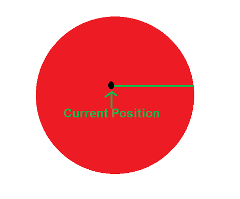
Filled Circle
- Parameters
- radius = the radius of the circle in the set [0,65535].
- Assumptions
- The user has set the current position and the current color.
- The user has initialized the MCU's SPI interface with the EZLCD_INIT_SPI() macro.
- The user has set the MCU's SPI pins to inputs and outputs appropriately.
- SS_BAR = OUTPUT
- SCK = OUTPUT
- MOSI = OUTPUT
- MISO = INPUT
This function is used to draw an unfilled ellipse as shown below from the current position in the current color at the current pen width and current pen height .
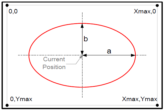
Unfilled Ellipse
- Parameters
- semi_major_axis = length of the semi-major axis (length a in the image above.) in the set [0,65535].
- semi_minor_axis = length of the semi-minor axis (length b in the image above.) in the set [0,65535].
- Assumptions
- The user has set the current position ,the current color , the current pen width, and the current pen height
- The user has initialized the MCU's SPI interface with the EZLCD_INIT_SPI() macro.
- The user has set the MCU's SPI pins to inputs and outputs appropriately.
- SS_BAR = OUTPUT
- SCK = OUTPUT
- MOSI = OUTPUT
- MISO = INPUT
This function is used to draw a elliptical arc as shown below from the current position in the current color at the current pen width and current pen height .
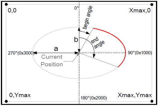
Elliptical Arc
- Parameters
- semi_major_axis = length of the semi-major axis (length a in the image above.) in the set [0,65535].
- semi_minor_axis = length of the semi-minor axis (length b in the image above.) in the set [0,65535].
- start_angle = the angle at which drawing will begin in the set [0,16384].
- end_angle = the angle at which drawing will end in the set [0,16384].
- Assumptions
- The user does not exceed the angle limits. The ezLCD+103 only understands positive angles from 0 to 360 degrees. Anything greater renders extremely slowly and is undefined.
- The user has set the current position ,the current color , the current pen width, and the current pen height
- The user has initialized the MCU's SPI interface with the EZLCD_INIT_SPI() macro.
- The user has set the MCU's SPI pins to inputs and outputs appropriately.
- SS_BAR = OUTPUT
- SCK = OUTPUT
- MOSI = OUTPUT
- MISO = INPUT
| void ezLCD_draw_ellipse_fill |
( |
uint16_t |
semi_major_axis, |
|
|
uint16_t |
semi_minor_axis |
|
) |
| |
This function is used to draw a filled ellipse as shown below from the current position in the current color .
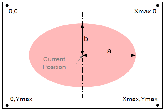
Filled Ellipse
- Parameters
- semi_major_axis = length of the semi-major axis (length a in the image above.) in the set [0,65535].
- semi_minor_axis = length of the semi-minor axis (length b in the image above.) in the set [0,65535].
- Assumptions
- The user has set the current position and the current color.
- The user has initialized the MCU's SPI interface with the EZLCD_INIT_SPI() macro.
- The user has set the MCU's SPI pins to inputs and outputs appropriately.
- SS_BAR = OUTPUT
- SCK = OUTPUT
- MOSI = OUTPUT
- MISO = INPUT
This function is used to draw a elliptical pie as shown below from the current position in the current color.
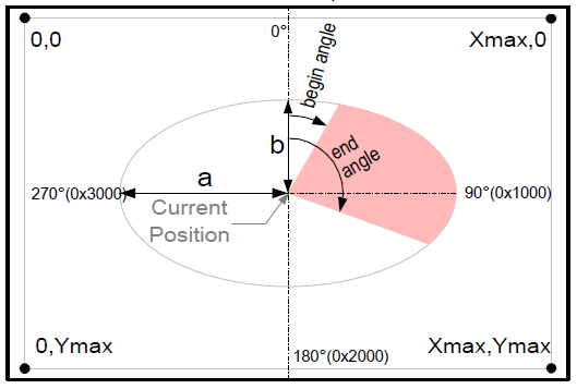
Elliptical Pie
- Parameters
- semi_major_axis = length of the semi-major axis (length a in the image above.) in the set [0,65535].
- semi_minor_axis = length of the semi-minor axis (length b in the image above.) in the set [0,65535].
- start_angle = the angle at which drawing will begin in the set [0,16384].
- end_angle = the angle at which drawing will end in the set [0,16384].
- Assumptions
- The user does not exceed the angle limits. The ezLCD+103 only understands positive angles from 0 to 360 degrees. Anything greater renders extremely slowly and is undefined.
- The user has set the current position and the current color.
- The user has initialized the MCU's SPI interface with the EZLCD_INIT_SPI() macro.
- The user has set the MCU's SPI pins to inputs and outputs appropriately.
- SS_BAR = OUTPUT
- SCK = OUTPUT
- MOSI = OUTPUT
- MISO = INPUT
This function is used to draw a pie as shown below from the current position in the current color .
Pie
- Parameters
- radius = the radius of the arc in the set [0,65535].
- start_angle = the angle at which drawing will begin in the set [0,16384].
- end_angle = the angle at which drawing will end in the set [0,16384].
- Assumptions
- The user does not exceed the angle limits. The ezLCD+103 only understands positive angles from 0 to 360 degrees. Anything greater renders extremely slowly and is undefined.
- The user has set the current position and the current color.
- The user has initialized the MCU's SPI interface with the EZLCD_INIT_SPI() macro.
- The user has set the MCU's SPI pins to inputs and outputs appropriately.
- SS_BAR = OUTPUT
- SCK = OUTPUT
- MOSI = OUTPUT
- MISO = INPUT
 1.8.5
1.8.5

